
This article continues where the first part of this system explanation ended, with the Dual Battery Charging and Solar Setup Wiring Diagrams. If you did not look at this previous article, you should check it out, as that article also covers setting up and configuring your Victron System Components.
In this article, we go through the power distribution and switching arrangements for all of the loads that make up a typical overland rig or camper setup.
Dual Battery Load Distribution
In the wiring diagram below, power comes from the dual battery bank on the left, labelled “Supply From Battery Bank”, which is connected directly to the 60 Amp Midi input fuse on the main distribution panel.
The reason there is a fuse in both this diagram and the previous diagram is due to the cable length (~approx 0.6m) between the charge supply circuit mounted in the adjacent wall of the Troopy and the battery bank (distribution panel). There is a chance that, even with the chargers off or isolated, there could be a fault on the cable, where the batteries are the source of the fault current. This fuse (“Charging Circuit Input”) protects against this situation.

Dual Battery Distribution Wiring Diagram Notes
From the diagram, refer to the additional notes below, where specific items are called out.
Main Fuses & Power Distribution (Note 1)

The function of the main fuse and distribution power is to act as the central source of power for the main loads, which are:
- Water Heater Duoetto MK2 Electric 10L Storage
- 2000W Inverter
- ARB Twin Compressor
- Load Supply (i.e. Power to fridge, charging points, lights, USB sockets and electric blanket, etc)
- Input supply from the Redarc & Victron charging system
12V Relay Control and Fuses (Note 2 & 3)
Connection to individual loads that need to be relay switched or fused is via Bussman (Eaton) 15300 Series Rear Terminal Fuse and Relay Boxes (RTMR). The Bussman RTMR 15303-5 Fuse & Relay distribution unit for relay-switched loads like the water heater and pumps, with their associated fuses. The RTMR 15303-1 is used for loads only requiring a fuse, like the fridge, charging points and lights.
The location’s purpose and the identities of each fuse or relay are shown in the table below.
Note 3: For the “Fuses 1 to n” on the diagram, refer to the “Righthand Panel” fuses 1 to 20 in the table.

Dashboard Switch Mounted on the PVS 78-Series Switch Panel (Note 4)

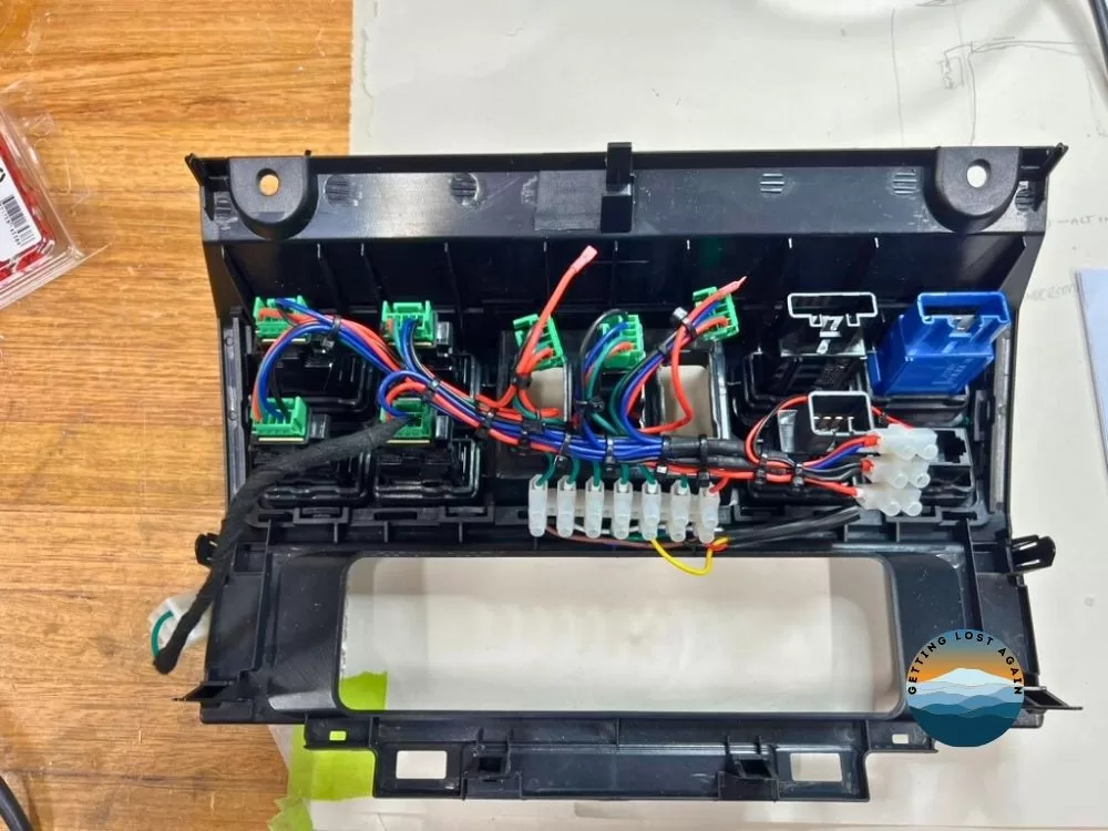
The main switches for the pumps, compressor, induction and rear working lights are all located in the centre dash, mounted in an aftermarket switch panel which replaces the original from PVS. This gives 11 switch locations, 3 of which are used up by the OEM switches for the fuel tank changeover, antenna and traction control. I also mounted the UHF pass-thru connector there for the GME UHF radio we have installed.
7-Core Cable (Note 5)
The simplest way to connect between the switches in the dash (see note 4) and the main 12-volt system, fuse panel and relays is to use a single 7-core or 11-core cable. The cable I used is 0.5mm per core and provides enough spares to use all the switch locations in the dash back to relays. The load capability of this cable must be de-rated to avoid heat damage.
Common Negative Buss Bars (Note 6)
All negative connections to and from the system are connected to a 500-amp main return post on the shunt or a 200-amp negative bus.
Terminal Bars and System Connections


Useful Info Fuse Guide


Heads Up – We support this blog using some affiliate promotion
This blog requires time and money; we provide you with genuine content and strive to offset its operating costs through affiliate promotions and other offers. There are links in this article to products that we have used, and some we think could be of interest and relevance to this article. Purchases using the link have no impact on you, but help us out tremendously. Thanks for your support.